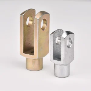
Pinned Rod and Cylinder Connections
Clevis ends create a straightforward pinned connection for rods, actuator eyes, and cylinder attachments where the clevis pin provides the pivot. Check pin fit, side clearance, shear load, and retention details.
Recherchez par référence, série, matériau, application ou spécification.
Appuyez sur Entrée pour voir tous les résultats Échap pour fermer

 metric-related-product
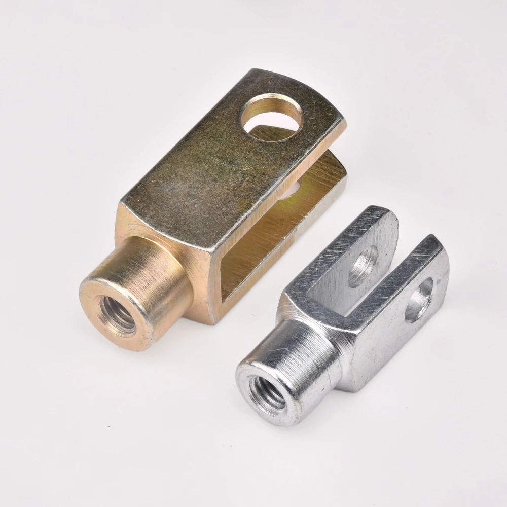
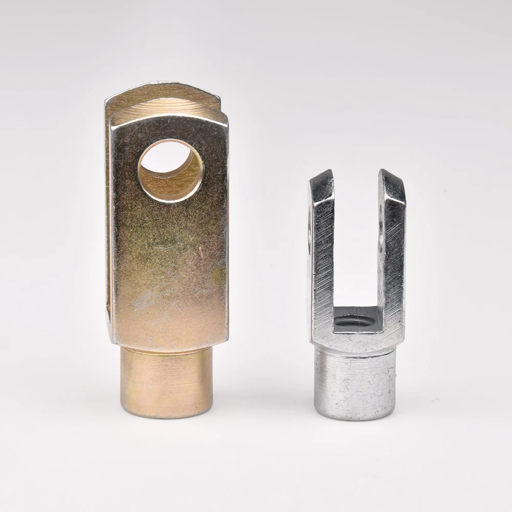
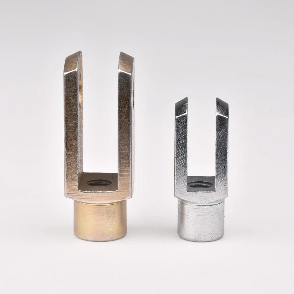
G 4×8 est une chape métrique de série G avec filetage M4, alésage d’axe (d4) de 1 mm et longueur d’axe (l8) de 1 mm. Largeur du corps (w3) = 8 mm, longueur hors tout du corps (l2) = 21 mm. Poids approximatif : 5 g.
Fabriqué en acier Q235 avec zinguage argent. La chape de série G est un embout à fourche femelle qui reçoit un axe de chape dans son alésage, permettant une connexion articulée à un support ou un œil de tringlerie complémentaire. L’extrémité filetée se raccorde à un actionneur métrique, à une tige de vérin ou à un adaptateur de tube. Utilisé dans les tringleries de vérins pneumatiques, les commandes d’automatisation, les actionneurs de vannes et les ensembles de chapes métriques polyvalents.
Filetage à gauche disponible — ajoutez le suffixe ‘LH’ (ex. G×4x8LH). Versions en acier inoxydable et aluminium disponibles sur demande. Axe de chape, rondelle et goupille fendue disponibles séparément. Option chape à goupille élastique disponible.
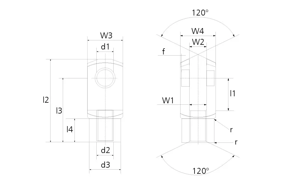
All available sizes in the G CLEVIS METRIC series. Can’t find your size? Contact us for custom dimensions.
| Part NO. | THREAD d2 | d1 H9 | l1 +0.5 -0.5 | w3 | w4 | w1 | w2 | d3 | l2 +0.5 -0.5 | l3 | l4 | APPROX WEIGHT (GRAM) |
|---|---|---|---|---|---|---|---|---|---|---|---|---|
| G 4x8 | M4 | 4 | 8 | 8 | 8 | 4 | 4 | 8 | 21 | 16 | 6.0 | 5 |
| G 4x16 | M4 | 4 | 16 | 8 | 8 | 4 | 4 | 8 | 29 | 24 | 6.0 | 7 |
| G 5x10 | M5 | 5 | 10 | 10 | 10 | 5 | 5 | 9 | 26 | 20 | 7.5 | 9 |
| G 5x20 | M5 | 5 | 20 | 10 | 10 | 5 | 5 | 9 | 36 | 30 | 7.5 | 13 |
| G 6x12 | M6 | 6 | 12 | 12 | 12 | 6 | 6 | 10 | 31 | 24 | 9.0 | 15 |
| G 6x24 | M6 | 6 | 24 | 12 | 12 | 6 | 6 | 10 | 43 | 36 | 9.0 | 21 |
| G 8x16 | M8 | 8 | 16 | 16 | 16 | 8 | 8 | 14 | 42 | 32 | 12.0 | 37 |
| G 8x16FG | M8X1 | 8 | 16 | 16 | 16 | 8 | 8 | 14 | 42 | 32 | 12.0 | 37 |
| G 8x32 | M8 | 8 | 32 | 16 | 16 | 8 | 8 | 14 | 58 | 48 | 12.0 | 54 |
| G 8x32FG | M8X1 | 8 | 32 | 16 | 16 | 8 | 8 | 14 | 58 | 48 | 12.0 | 54 |
| G 10x20 | M10 | 10 | 20 | 20 | 20 | 10 | 10 | 18 | 52 | 40 | 15.0 | 74 |
| G 10x20FG | M10X1.25 | 10 | 20 | 20 | 20 | 10 | 10 | 18 | 52 | 40 | 15.0 | 74 |
| G 10x40 | M10 | 10 | 40 | 20 | 20 | 10 | 10 | 18 | 72 | 60 | 15.0 | 116 |
| G 10x40FG | M10X1.25 | 10 | 40 | 20 | 20 | 10 | 10 | 18 | 72 | 60 | 15.0 | 116 |
| G 12x24 | M12 | 12 | 24 | 24 | 24 | 12 | 12 | 20 | 62 | 48 | 18.0 | 121 |
| G 12x24FG | M12X1.25 | 12 | 24 | 24 | 24 | 12 | 12 | 20 | 62 | 48 | 18.0 | 121 |
| G 12x48 | M12 | 12 | 48 | 24 | 24 | 12 | 12 | 20 | 86 | 72 | 18.0 | 175 |
| G 12x48FG | M12X1.25 | 12 | 48 | 24 | 24 | 12 | 12 | 20 | 86 | 72 | 18.0 | 175 |
| G 14x28 | M14 | 14 | 28 | 27 | 27 | 14 | 14 | 24 | 72 | 56 | 22.5 | 178 |
| G 14x28FG | M14X1.5 | 14 | 28 | 27 | 27 | 14 | 14 | 24 | 72 | 56 | 22.5 | 178 |
| G 14x56 | M14 | 14 | 56 | 27 | 27 | 14 | 14 | 24 | 101 | 85 | 22.5 | 258 |
| G 14x56FG | M14X1.5 | 14 | 56 | 27 | 27 | 14 | 14 | 24 | 101 | 85 | 22.5 | 258 |
| G 16x32 | M16 | 16 | 32 | 32 | 32 | 16 | 16 | 26 | 83 | 64 | 24.0 | 282 |
| G 16x32FG | M16X1.5 | 16 | 32 | 32 | 32 | 16 | 16 | 26 | 83 | 64 | 24.0 | 282 |
| G 16x64 | M16 | 16 | 64 | 32 | 32 | 16 | 16 | 26 | 115 | 96 | 24.0 | 411 |
| G 16x64FG | M16X1.5 | 16 | 64 | 32 | 32 | 16 | 16 | 26 | 115 | 96 | 24.0 | 411 |
| G 18x36 | M18 | 18 | 36 | 36 | 36 | 18 | 18 | 30 | 94 | 72 | 27.0 | 390 |
| G 18x36FG | M18X1.5 | 18 | 36 | 36 | 36 | 18 | 18 | 30 | 94 | 72 | 27.0 | 390 |
| G 20x40 | M20 | 20 | 40 | 40 | 40 | 20 | 20 | 34 | 105 | 80 | 30.0 | 550 |
| G 20x40FG | M20X1.5 | 20 | 40 | 40 | 40 | 20 | 20 | 34 | 105 | 80 | 30.0 | 550 |
| G 20x80 | M20 | 20 | 80 | 40 | 40 | 20 | 20 | 34 | 145 | 120 | 30.0 | 800 |
| G 20x80FG | M20X1.5 | 20 | 80 | 40 | 40 | 20 | 20 | 34 | 145 | 120 | 30.0 | 800 |
| G 25x50 | M24 | 25 | 50 | 50 | 50 | 25 | 25 | 42 | 132 | 100 | 36.0 | 1100 |
| G 25x50FG | M24X2 | 25 | 50 | 50 | 50 | 25 | 25 | 42 | 132 | 100 | 36.0 | 1100 |
| G 28x56 | M27 | 28 | 56 | 55 | 55 | 28 | 28 | 48 | 148 | 112 | 40.0 | 1500 |
| G 28x56FG | M27X2 | 28 | 56 | 55 | 55 | 28 | 28 | 48 | 148 | 112 | 40.0 | 1500 |
| G 30x54FG | M27X2 | 30 | 54 | 55 | 55 | 30 | 30 | 48 | 148 | 110 | 40.0 | 1440 |
| G 30x60 | M30 | 30 | 60 | 60 | 60 | 30 | 30 | 52 | 160 | 120 | 42.0 | 1970 |
| G 30x60FG | M30X2 | 30 | 60 | 60 | 60 | 30 | 30 | 52 | 160 | 120 | 42.0 | 1970 |
| G 35x54FG | M36X2 | 35 | 54 | 70 | 70 | 35 | 35 | 60 | 188 | 144 | 54.0 | 2930 |
| G 35x72 | M36 | 35 | 72 | 70 | 70 | 35 | 35 | 60 | 188 | 144 | 54.0 | 2930 |
| G 35x72FG | M36X2 | 35 | 72 | 70 | 70 | 35 | 35 | 60 | 188 | 144 | 54.0 | 2930 |
| G 36x72 | M36 | 35 | 72 | 70 | 70 | 36 | 36 | 60 | 188 | 144 | 54.0 | 2930 |
| G 36x72FG | M36X2 | 35 | 72 | 70 | 70 | 36 | 36 | 60 | 188 | 144 | 54.0 | 2930 |
| G 40x84FG | M42X2 | 40 | 84 | 85 | 85 | 40 | 40 | 70 | 232 | 168 | 63.5 | 5640 |
| G 42x84 | M42 | 42 | 84 | 85 | 85 | 42 | 42 | 70 | 232 | 168 | 63.5 | 5340 |
| G 42x84FG | M42X2 | 42 | 84 | 85 | 85 | 42 | 42 | 70 | 232 | 168 | 63.5 | 5340 |
| G 50x96 | M48 | 50 | 96 | 96 | 96 | 50 | 50 | 82 | 265 | 192 | 73.0 | 7860 |
| G 50x96FG | M48X2 | 50 | 96 | 96 | 96 | 50 | 50 | 82 | 265 | 192 | 73.0 | 7860 |
Material certifications verified. Composition confirmed by spectrometer before machining begins.
100% go/no-go gauge check on all threaded sections. Zero tolerance on dimensional non-conformance.
Static and dynamic load tests run on representative samples from each production batch.
CMM verification of critical dimensions — ball diameter, bore, thread pitch, and body length.
Visual and tactile inspection for burrs, scratches, surface cracks, and plating defects.
Misalignment angle and torque measured to confirm liner performance meets specification.
Hardness tests confirm proper heat treatment on chromoly steel bodies and bearing balls.
Full traceability from raw material heat number to finished part. COC and inspection reports available.
Share your part number, required quantity, and any special material or packaging requirements. We respond within 24 hours.
The G 4x8 is a metric G-series clevis with a M4 threaded stud end and a 4 mm pin bore, built as a female fork fitting for pneumatic cylinder linkages, automation controls, valve actuators, and general-purpose metric clevis assemblies. The threaded end connects to a mating actuator, cylinder rod, or tube adapter, while the bore accepts a clevis pin so the fitting can pivot against a bracket or linkage eye.
The G 4x8 is threaded M4, a standard metric (coarse) pitch — SYZ does not list a fine-pitch "FG" variant at this bore/length combination, so this is the only pitch offered for this size.
Pin bore (d1) is 4 mm and pin length (l1) is 8 mm, sized to take a 4 mm clevis pin through the fork bore for the articulated connection.
Overall body length (l2) is 21 mm, body width (w3) is 8 mm, hub diameter (d3) is 8 mm, and fork throat depth (l4) is 6.0 mm. Approximate weight is 5 g (0.01 kg) — check these against your linkage clearance and handling requirements before ordering.
Standard construction is Q235 steel with a silver zinc-plated finish. Stainless steel and aluminum versions are available on request — confirm material and finish when requesting a quote.
Yes. Standard thread hand is right-hand; add "LH" to the part number (e.g., G×4x8LH) to order the left-hand thread version for turnbuckle-style or opposing-thread linkage builds. Clevis pin, washer, and cotter pin are available separately, and a spring-pin clevis option is also offered.